Specification of Lifting System
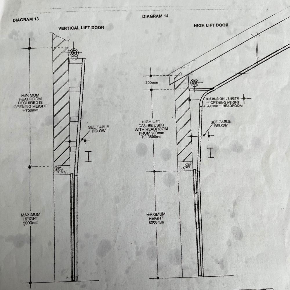
The specifier should select the system best suited to the headroom available and also consider the internal traffic clearance under the door. Overhead ganty cranes may cause a need to select “High” or “Vertical” lift systems to avoid conflict between movement of crane and opened doors
Standard Lift Doors, as illustrated in diagram 10 below are the most economic of the springing systems and the opened door is situated at a height slightly greater than the clear height of the opening.

Doors in excess of 3000mm height are fitted with reduction geared continuous handchain operators and are fitted to either end of the torsion shaft (See dioagram 1). The overhead track is sloped at approximately 5deg so that the door will loewr under its own weight as the handchain rotates the torsion shaft, releasing cable from the cable spools. The table in diagram 10 shows the headroom (see MH) required to maintain the 5deg slope according to the door height.
Where the headroom is in excess of 2000mm, the use of a hight lift system is recommended. The track hangers supporting the overhead tracks may otherwise become too long and require costly additional bracing in order that they may be stabilised.
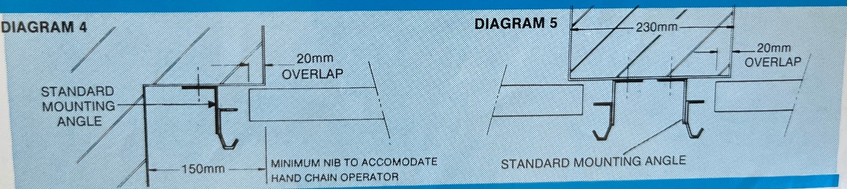
IMPORTANT NOTE: Brick cavities and hoowl blocks should be filled solid with mortar for a width of 230mm minimum at nibs to enable the track mounting angles to be fixed securely. with expanding bolts.
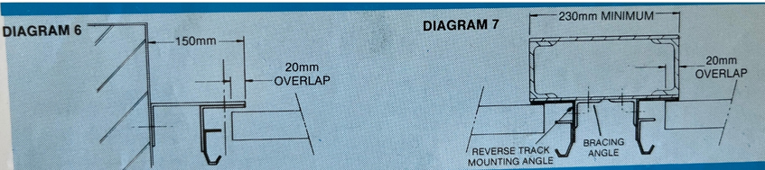
In diagram 6 above, a “No Nob” situation is shown. A false nib 150mm wide formed of 4mm stel can be provided wich provides sufficient spact to allow the use of a hand chain operator. it is often necessary to provide intermediate mullions to reduce over-wide openings. Typical construction and overall size is illustrated in diagram 7.
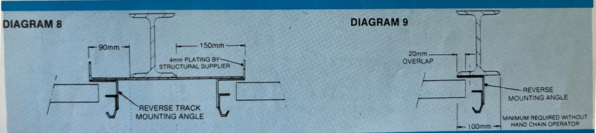
Diagram 8 illustrates the situation where a structural steel column has been plated out to provide sufficient nib due to gusset overhead precluding direct fixing to the flange of the column. The left had plating of 90mm is sufficient for track handling. The right hadn plating of 150mm is sufficient for track and hand chain operator. Diagram 9 illustrates standard fixing to structure where height requirement and the need for hand chain operator poses no problem.